
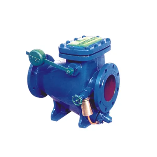
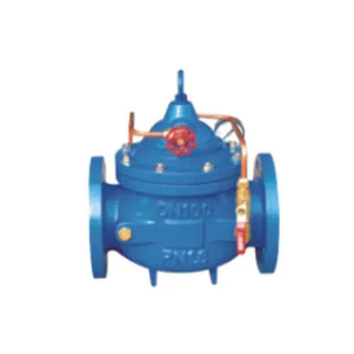
Slow closing check valve is installed in the pump outlet,high-rise building water supply systems and other water supply system to prevent the media badk,intelligent valve phenomenon of water hammer and the water hammer.The vaive both electic valve,chedk vaive and water hammer eliminator three functions,which can effedively improve the safety and reliability of water supply system.And the sow opening,fast closing,slow dosing to eliminate the technical prinaiples of integrated water hammer, prevent the generation of water hammer and open the pump water hammer.Only by operating the pump motor hoist button,the valve can open and dose automatically aocording to the water pump operation,large fow rate,the pressure loss of water.The following applies to DN600 diameter vave.
The main dimensions
DN | 20 | 25 | 32 | 40 | 50 | 65 | 80 | 100 | 125 | 150 | 200 | 250 | 300 | 350 | 400 | 450 |
L | 150 | 160 | 180 | 200 | 203 | 216 | 241 | 292 | 330 | 356 | 495 | 622 | 698 | 787 | 914 | 978 |
H1 | 106 | 106 | 106 | 137 | 137 | 145 | 178 | 232 | 286 | 318 | 413 | 502 | 600 | 638 | 677 | 677 |
H | 172 | 172 | 172 | 225 | 225 | 270 | 289 | 375 | 420 | 570 | 722 | 769 | 906 | 1025 | 1027 | 1027 |
Slow closing check valve: Comprehensive Guide for Industrial and Commercial Applications
The slow closing check valve is an advanced type of check valve designed to prevent water hammer, pressure surges, and pipeline damage by allowing gradual and controlled closure. Unlike standard check valves that may close abruptly, the slow closing design reduces shock to the system, ensuring longer equipment life, safer operation, and reduced maintenance costs.
Widely used in industrial pipelines, water supply systems, HVAC networks, chemical processing, and municipal infrastructure, this valve combines robust construction, precision engineering, and low maintenance requirements.
This guide provides a comprehensive overview covering product introduction, technical parameters, safety instructions, and maintenance/upgrade plans, making it an essential reference for engineers, operators, and procurement teams.
Slow Closing Mechanism: Ensures controlled valve closure to reduce water hammer.
Durable Construction: Manufactured with stainless steel, cast iron, bronze, or high-quality alloys for long-term reliability.
Wide Application Range: Suitable for water, gas, steam, and various chemical fluids.
Low Maintenance: Simple internal design reduces wear and service frequency.
Versatile Sizes and Pressure Ratings: Fits a broad spectrum of pipelines and operational conditions.
The slow closing check valve operates using a dampened closing mechanism, typically involving spring-assisted or hydraulic damping components. When the flow reverses, the valve disc closes gradually instead of slamming shut, absorbing kinetic energy and preventing pressure spikes.
Prevents water hammer and pipeline damage.
Enhances system safety and operational reliability.
Reduces wear on downstream equipment such as pumps and pipes.
Supports compliance with industrial safety standards.
| Specification | Typical Range / Details |
|---|---|
| Valve Type | Slow closing, swing or piston type |
| Size Range | DN15 – DN500 mm |
| Pressure Rating | PN10 – PN100, Class 150 – 600 |
| Body Material | Stainless steel, cast iron, bronze |
| Seat Material | PTFE, NBR, EPDM, or metal |
| End Connections | Flanged, threaded, or welded |
| Temperature Range | -40°C to 200°C depending on material |
| Applicable Media | Water, steam, gas, chemical fluids |
| Closing Mechanism | Spring-assisted, hydraulic damped |
| Flow Direction | Marked on body for correct installation |
Technical Tips:
Verify pipe diameter, pressure rating, and media compatibility before installation.
Ensure that the flow direction matches the marking on the valve body.
Select appropriate seat material for chemical resistance or temperature tolerance.
Proper use of the slow closing check valve ensures system integrity and operator safety.
Always depressurize the system before installation, inspection, or maintenance.
Avoid installation near sources of excessive vibration or mechanical shock.
Confirm that the valve material is compatible with the fluid to prevent corrosion or damage.
Do not exceed the maximum pressure or temperature ratings specified for the valve.
Ensure that flow is in the correct direction to maintain slow-closing functionality.
Periodically inspect for leaks, corrosion, or abnormal noise during operation.
If unexpected pressure surges occur, shut down the system and inspect valves immediately.
Replace worn or damaged damping components to restore safe operation.
Keep a spare valve or parts kit on hand for critical systems.

Inspect valve and pipeline for debris or damage.
Confirm valve specifications and flow direction.
Ensure access for future inspection and maintenance.
| Step | Description |
|---|---|
| Step 1 | Position valve according to flow marking |
| Step 2 | Secure using flanged, threaded, or welded connections |
| Step 3 | Adjust damping mechanism if adjustable |
| Step 4 | Gradually pressurize system and check for leaks |
| Step 5 | Observe initial closing to ensure smooth, controlled operation |
| Step 6 | Record pressure and system parameters for operational reference |
Operational Tips:
Avoid sudden system start-ups that may bypass damping mechanism.
Monitor downstream equipment for abnormal vibrations during initial operation.
Calibrate damping settings if adjustable to optimize closing speed.
| Component | Frequency | Maintenance Action |
|---|---|---|
| Valve Disc & Seat | Quarterly | Inspect for wear, debris, and smooth operation |
| Closing Mechanism | Semi-Annually | Check springs, hydraulic dampers, and lubricate if required |
| Valve Body | Annually | Inspect for corrosion, cracks, or leaks |
| Connections & Gaskets | Quarterly | Tighten and replace worn gaskets |
| System Test | Annually | Perform full operational and leak test |
Hydraulic damping enhancement for higher pressure systems.
Electronic monitoring integration for remote status and alerts.
Material upgrades for aggressive chemical media or extreme temperatures.
Flow path optimization for improved energy efficiency.
Maintenance Best Practices:
Keep a maintenance log including inspection dates and actions taken.
Replace parts with manufacturer-approved components.
Perform pressure testing after any maintenance to ensure safe operation.
Protects pipelines from pressure surges caused by pumps or sudden flow changes.
Extends equipment life and reduces repair costs.
Prevents pipe bursts and water hammer in municipal water networks.
Ensures smooth and consistent water flow.
Minimizes stress on pumps, heat exchangers, and valves.
Improves system efficiency and reliability.
Compatible with moderate chemical fluids.
Protects critical equipment and ensures safe fluid handling.
The slow closing check valve is a critical component for safe and efficient fluid management. Its controlled closure mechanism prevents water hammer, pressure surges, and pipeline damage, ensuring long-term reliability and operational safety.
With robust construction, versatile applications, and low maintenance requirements, this valve is ideal for industrial, municipal, and commercial fluid systems. By following proper installation, operational, and maintenance guidelines, users can maximize system longevity, reduce repair costs, and ensure safe and stable operation.
 RELATED
This website uses cookies to ensure you get the best experience on our website.


 Phone
Phone